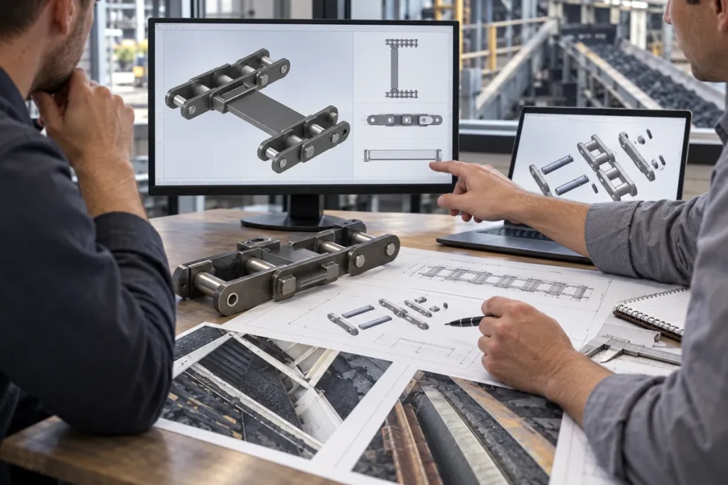
What to Check After a Feeder Breaker Chain Adjustment
After a feeder breaker chain adjustment, verify take-up position, strand balance, tracking, sprocket engagement, flight clearance, observations, and.
Engineering GuideUpdated September 16, 2026
A feeder breaker chain adjustment changes the relationship between the chain, take-up system, sprockets, flights, and conveyor path. Treating the wrench turn or take-up movement as the end of the job misses the most important question: did the machine return to the expected operating condition without creating a new problem?
The correct post-adjustment checks are machine dependent, so this article does not publish a universal chain sag, take-up dimension, or tension value. Those settings must come from the feeder breaker manufacturer, approved drawing, maintenance procedure, or controlled site standard. What can be standardized is the evidence: record the condition before adjustment, record exactly what changed, and inspect the chain/system relationship afterward.
This approach is particularly useful when a chain has needed repeated adjustment. A detailed before-and-after record can show whether the adjustment is compensating for normal service change, uneven strand condition, sprocket engagement, tracking, repair history, or another issue that deserves broader review.
Before
Record take-up position, reason for adjustment, chain location, and visible symptoms before anything moves.
After
Verify both strands/sides as applicable, tracking, sprocket engagement, flight clearance, and retention condition.
Follow up
Reinspect under the controlled procedure after initial operation and compare the new condition with the pre-adjustment evidence.
1. Confirm Exactly What Was Adjusted
Start the post-adjustment record with the mechanism that moved: screw take-up, hydraulic arrangement, another machine-specific device, or a component replacement that effectively changed chain length. Record the before and after positions using the machine’s own reference scale or a defined field reference. If two sides are independently adjustable, keep the left and right values separate.
Also record the reason. Was the chain visibly slack under the approved criterion, was engagement poor, did a flight contact structure, was a new section installed, or did the maintenance procedure call for a routine check? The same final take-up position can mean different things depending on why the adjustment began.
2. Check Side-to-Side or Strand Balance Where the Machine Uses Parallel Chains
Feeder breaker scraper systems commonly involve paired chain paths. If the machine uses independently adjustable sides, verify that the adjustment did not leave one strand carrying a visibly different geometric relationship. Compare take-up references, corresponding flights, and alignment through the accessible path. Use the machine procedure to define the required balance rather than applying a generic web value.
Unequal adjustment can show up as skewed flights, side contact, unusual pin or link loading, or poor sprocket engagement. A photograph looking across a representative flight can reveal whether the two strands appear synchronized. If the system has a designed offset, document that design instead of treating visual symmetry as the only criterion.
3. Inspect Sprocket Engagement Before Declaring the Adjustment Successful
Observe how the chain approaches, seats, and leaves the accessible sprocket under the approved inspection condition. Look for climbing, hesitation, unusual side contact, or a chain that does not settle consistently into the tooth spaces. Record the sprocket tooth condition at the same time, because a worn or misaligned sprocket can make a chain adjustment appear ineffective.
Do not diagnose by noise alone. A change in sound can be useful evidence, but it should be paired with visual and dimensional observations. If the chain still engages abnormally after a controlled adjustment, stop repeating the same adjustment and widen the inspection to wear, alignment, sprocket condition, and chain configuration.
4. Follow the Chain Path and Look for New Contact
Check guides, pans, casing, transitions, and other accessible areas where links or flights can contact the machine. An adjustment that reduces slack at one point can shift where the chain runs elsewhere. Fresh polishing, scoring, flight-edge contact, or a changed clearance deserves documentation before extended operation.
Compare with pre-adjustment photographs if available. The important question is whether contact changed, not whether a surface simply looks used. If the machine uses replaceable wear components or deliberate guiding surfaces, distinguish designed contact from abnormal interference using the machine documentation.
5. Inspect Flights for Squareness and Consistent Spacing
Look across several flights or scraper bars and check whether they remain square to the chain path as expected by the installed configuration. A skewed flight after adjustment can indicate unequal strand position, local damage, a mismatched chain section, or an attachment problem. Record flight spacing at defined reference points when the investigation involves synchronization.
For K201B and K207B, the documented repeating unit contains one Flight Section and two Chain Sections. That information can help organize a known-model inspection, but it should not be used as a universal rule for an unidentified chain. Record the pattern that is actually installed.
6. Recheck Joint and Retention Features Near Work Areas
If the adjustment required chain disassembly, section replacement, or work near connecting hardware, inspect the disturbed joints and retention features before operation under load. Confirm that visible pins, T-pins, spring pins, fasteners, or other retention elements match the approved assembly and are fully seated as required by the controlled procedure.
A post-adjustment problem can come from the adjustment itself or from an assembly detail disturbed during the same maintenance event. Keeping those possibilities visible prevents technicians from chasing take-up position while a local joint issue remains unresolved.
7. Observe Initial Operation Under the Approved Restart Procedure
During the controlled restart, watch for tracking changes, repeated impact, irregular flight movement, unusual engagement, or contact that was not present before the work. The observer should stand in the designated safe position and use the machine procedure for any stop-and-inspect cycle. Do not approach moving chain to obtain a closer view.
Record what changed compared with the original symptom. If the symptom disappears, note the operating condition under which it was checked. If it persists or changes form, stop treating the job as a simple adjustment and route the evidence into a troubleshooting review.
Post-adjustment verification record
Check
Before/after evidence
Escalation trigger
Take-up position
Separate values for each adjustable side using the same reference
Unexpected or unequal movement that cannot be explained by the procedure.
Sprocket engagement
Photos/observations of approach, seating, and exit
Climbing, repeated impact, unusual side contact, inconsistent seating.
Tracking/contact
Guide, pan, casing, transition observations
New polishing, scoring, or interference after adjustment.
Flights
Squareness, spacing, attachment condition
Skewing, changed spacing, damaged or loose attachment.
Joints/retention
Disturbed areas checked against approved assembly
Missing, displaced, or uncertain retention feature.
Initial run
Observed symptom before vs after adjustment
Symptom persists, changes, or new abnormal behavior appears.
Record rule
The acceptance setting comes from the machine-specific procedure. This record controls the before-and-after evidence and the decision to widen the inspection.
8. Schedule a Follow-Up Check Based on the Controlled Maintenance Plan
A chain can settle after work, and a newly replaced section can change the system relationship. Use the machine or site maintenance plan to decide when the next observation is required. The follow-up should repeat the same take-up reference, location, and photographs whenever practical so the change is comparable.
This article deliberately does not prescribe “check after X hours” because operating duty, chain design, and machine instructions differ. The engineering principle is repeatability: whatever interval controls the follow-up, use the same evidence fields so the result can be compared rather than merely noted.
9. Escalate Repeated or Uneven Adjustment Instead of Chasing a Setting
If one side repeatedly needs more movement, the chain continues to climb or strike, or adjustment range is being consumed faster than expected, widen the investigation. Inspect multi-pitch chain measurements, joint articulation, sprocket tooth condition, shaft/track alignment, flight damage, material build-up, and repair history. A take-up is a control mechanism, not a substitute for identifying the cause of abnormal change.
Preserve each adjustment event in chronological order. The history can show whether the condition is progressive, localized, linked to a component replacement, or associated with a particular operating period. That trend is often more diagnostic than the latest take-up position by itself.
Adjustment event
A controlled change to the chain take-up or related geometry recorded with before-and-after evidence.
Post-adjustment verification
Checks that confirm the chain, sprockets, flights, and machine path behave as expected after the change.
Repeated adjustment
A pattern of successive take-up changes that should be reviewed as diagnostic evidence rather than treated as isolated events.
Escalation
The decision to stop simple adjustment and investigate wear, engagement, alignment, configuration, or another underlying cause.
Use this handoff checklist to close the field record for What to Check After a Feeder Breaker Chain Adjustment. The goal is not to create another generic maintenance form. It is to preserve the specific observations, reference points and machine context that the next reviewer needs in order to understand how the result was obtained. Keep machine-specific acceptance limits under the approved drawing, maintenance procedure or engineering instruction rather than inventing a universal web value.
Checkpoint
What to record
How the record is used
Confirm Exactly What Was Adjusted
Record the exact machine location, strand or side, current operating/shutdown state, and the observation that relates to confirm exactly what was adjusted. Include a photograph that lets another reviewer find the same area.
Establishes the context so later measurements are not detached from the machine and chain position.
Check Side-to-Side or Strand Balance Where the Machine Uses Parallel Chains
Capture the physical reference used for check side-to-side or strand balance where the machine uses parallel chains. Keep the raw dimension, image or marking beside the interpretation, and note any wear, repair, build-up or access limitation that could affect the reading.
Makes the result repeatable and prevents a damaged or poorly defined reference from becoming the replacement requirement.
Inspect Sprocket Engagement Before Declaring the Adjustment Successful
Cross-check inspect sprocket engagement before declaring the adjustment successful against any controlled drawing, previous purchase reference or retained spare that is available. Keep current field data and historical information in separate fields when they differ.
Preserves traceability when field condition, historical records and nominal product information do not agree perfectly.
Follow the Chain Path and Look for New Contact
For follow the chain path and look for new contact, state what is confirmed, what is only observed, and what still needs engineering confirmation. Attach the image or measurement that supports the statement rather than relying on a product name alone.
Gives maintenance, purchasing and the supplier a clear list of what can be acted on now and what must be resolved before release.
Separate as-found condition from required replacement geometry. A worn, repaired, dirty or partially dismantled component may still be very useful for identification, but its current shape is not automatically the manufacturing requirement. Label field measurements as observed data, retain the original unit and measurement method, and identify any feature that may have been altered by service. For after feeder breaker chain adjustment checks, photographs should show the measurement endpoints or component relationship clearly enough that a remote reviewer can reproduce the logic.
Resolve conflicting information instead of hiding it. If a drawing, old order, marking and current measurement point in different directions, keep each source visible and describe the conflict. Do not average values or silently choose the most convenient one. Use additional photographs, measurements from another intact repeating unit, machine interface information and the controlled document revision to determine which value governs. If escalate repeated or uneven adjustment instead of chasing a setting cannot be confirmed during the shutdown, state that limitation explicitly so the open question survives the handoff.
Make the next action obvious for What to Check After a Feeder Breaker Chain Adjustment. The completed record should tell maintenance what should be rechecked, tell purchasing what information belongs in the RFQ, and tell engineering which dimensions or interfaces still need approval. Before the machine returns to service, confirm that the file set includes an overall machine view, a complete repeating chain/flight view, close-ups of relevant components or markings, and the dimensions used in this guide. For after feeder breaker chain adjustment checks, a traceable set of observations is more useful than a long narrative with no datum, and it reduces the risk that a replacement decision is made from pitch, appearance or an old part number alone.
Questions to Resolve Before the Next Decision
What tension should a feeder breaker chain have after adjustment?
Use the machine-specific maintenance procedure, approved drawing, or controlled site standard. This article does not publish a universal tension or sag value for feeder breaker chains.
Why check sprockets after changing take-up position?
Chain engagement and sprocket condition influence how the adjusted chain runs. A worn or misaligned sprocket can produce symptoms that repeated take-up changes will not correct.
Should both strands always have identical take-up positions?
Not as a universal rule. Use the machine design and procedure. Where independently adjustable parallel chains are intended to run in balance, record both sides and investigate unexplained differences.
What if the chain looks better immediately but needs another adjustment soon?
Preserve the history and widen the inspection to chain wear, sprocket engagement, alignment, flight condition, build-up, and repair history. Repeated adjustment is diagnostic evidence.
Next Step: Close the Technical Record
A feeder breaker chain adjustment is complete only when the post-adjustment system has been checked and the evidence recorded. Take-up position, strand relationship, sprocket engagement, tracking, flight condition, joints, and initial operation all contribute to that decision.
If the same symptom returns or one side repeatedly consumes adjustment, stop chasing a generic setting. Use the chronological record to guide a broader inspection of the chain and surrounding machine.