What to Include in a Custom Feeder Breaker Chain Drawing
A custom feeder breaker chain drawing should control pitch, repeating unit, flight geometry, links, pins/bushes, interfaces, units, tolerances.
Engineering GuideUpdated September 16, 2026
A custom feeder breaker chain drawing is not merely a clean version of field measurements. Its job is to define the geometry and requirements that manufacturing, inspection, installation, and repeat procurement will use. Every important field dimension must be tied to a datum and interface, and every customer-controlled material, heat-treatment, testing, or documentation requirement must be stated or intentionally left for engineering resolution.
The drawing becomes especially important when an installed chain does not match a known model, when a historic drawing conflicts with the machine, or when field repairs have obscured the original design. The drafting process should preserve the technical data evidence but avoid turning wear or repair geometry into a production requirement without approval.
This article describes the information architecture of a custom chain drawing. It does not invent material grades, hardness, tensile strength, tolerances, welding rules, or performance values. Those values must come from customer requirements, approved engineering calculations, validated product standards, or the responsible manufacturer’s design process.
Control the repeat
Define pitch, chain-section sequence, flight spacing, unit length, strand relationship, and direction/orientation where relevant.
Control the interfaces
Dimension pins, bushes, holes, attachment faces, scraper geometry, and sprocket-related datums needed for fit and engagement.
Control the revision
Use drawing number, revision, units, general notes, change history, approval status, and traceable source evidence.
1. Start with Drawing Identity and Scope
The title block should identify the assembly being controlled: complete feeder breaker chain, repeating unit, Chain Section, Flight Section, or specific component. Include drawing number, revision, date, units, scale where used, responsible approval, and project/customer reference under the organization’s document-control system.
State whether the drawing is for quotation review, approval, production, or reference. An uncontrolled RFQ sketch should not be mistaken for a released production drawing.
2. Define the Chain Centerline and Primary Datums
Choose datums that remain stable through manufacturing and inspection: chain centerlines, pin centers, controlled plate faces, flight centerline, or other functional features. Dimensions should originate from those datums rather than from cosmetic or wear-prone edges whenever possible.
The datum scheme should make field verification possible. If maintenance teams cannot identify the controlled faces on the installed chain, future replacement measurements will drift into convenient but non-equivalent references.
Functional datum
A reference feature chosen because it controls assembly, engagement, or repeatable inspection.
Repeating unit drawing
A view that shows the full chain-and-flight sequence before the same structural configuration recurs.
Customer-controlled requirement
A material, process, inspection, documentation, or interface requirement explicitly defined by the customer or approved specification.
Released drawing
A revision approved through the responsible document-control process for its stated production or procurement use.
Show nominal pitch between equivalent joint centers or the design-defined references. Add the pin, bush, plate-hole, spacing, projection, and retention geometry required to manufacture and inspect the joint. If an extended pin or T-pin is part of the design, define its orientation and relationship to the attachment.
Do not infer joint dimensions from a worn field sample without engineering review. Where source evidence is incomplete, flag the dimension for confirmation rather than filling it from a similar chain.
4. Define the Repeating Unit and Chain-Section Sequence
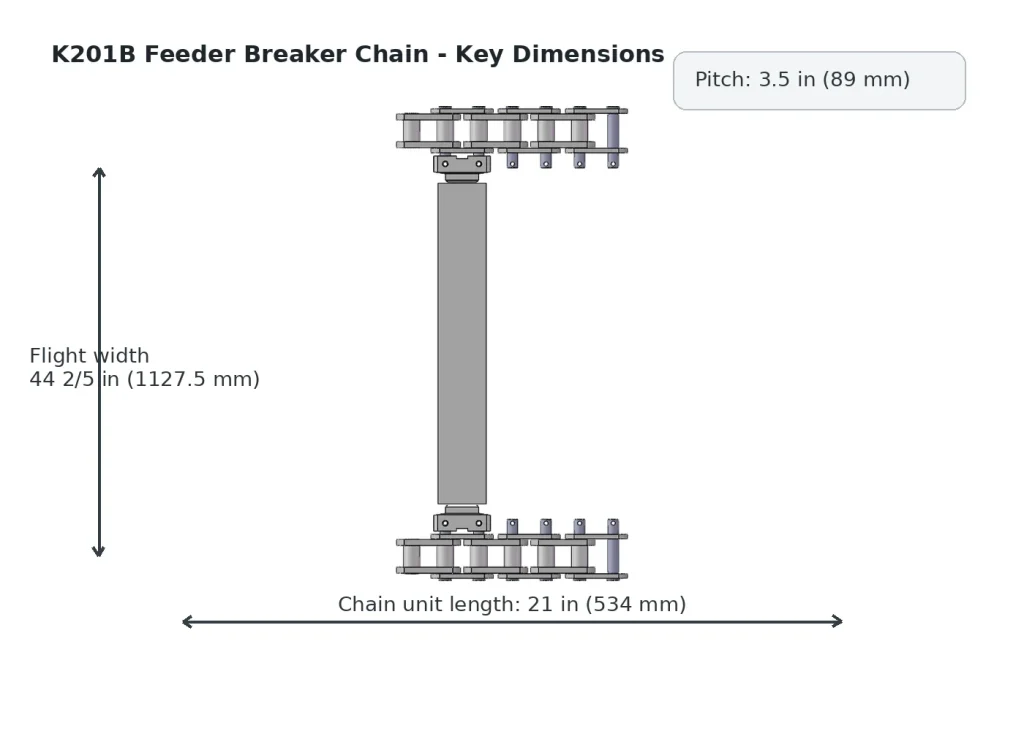
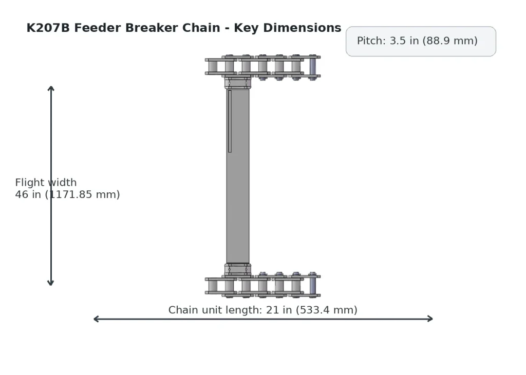
Draw enough chain to show one complete structural repeat and label Chain Sections, Flight Sections, special links, and interval counts. Dimension the unit length from equivalent datums and show how many pitches occur inside the repeat.
If the design alternates flight styles or uses a longer super-pattern, show the full pattern that must repeat in production. A short drawing view that hides the alternation can produce a technically correct individual link assembled into the wrong conveyor sequence.
5. Control Flight and Scraper Geometry
Dimension scraper/flight width from controlled faces, head and plate relationships, thicknesses where required, hole or pin positions, offsets, and the connection to each chain strand. Define flight spacing using structural datums rather than worn material-contact edges.
If the installed chain is being reverse-engineered, separate observed worn geometry from the approved restored geometry. The drawing should not preserve missing material as the new design.
6. Show Strand Relationship and Assembly Orientation
For paired chains, define center distance, synchronization relationship, left/right component differences if any, flight squareness, and orientation. Include travel direction or material-flow arrow when component orientation is directional and the organization’s drawing practice allows it.
An assembly drawing should also make clear whether a part is mirrored, handed, or common to both sides. That reduces workshop and installation ambiguity.
7. Define Sprocket and Machine Interfaces That Must Match
The chain drawing may not need to reproduce the entire sprocket, but it should control the joint geometry and other interfaces needed for compatible engagement. Where a sprocket drawing exists, cross-reference it. Include required clearances, attachment envelopes, or machine interface dimensions only when they are controlled engineering requirements.
Do not claim OEM interchangeability simply because the field chain fits an existing sprocket. The custom drawing should state the approved interfaces, not a marketing compatibility list unsupported by evidence.
8. State Materials, Heat Treatment, and Quality Requirements Only When Approved
If the customer controls material grade, heat treatment, hardness, surface treatment, inspection, traceability, or testing, place those requirements in the appropriate notes or component specifications. If they are not known, mark them for engineering definition rather than copying values from another manufacturer’s catalogue.
The same rule applies to strength and performance claims. A custom drawing should be supported by design validation; it is not the place to invent a tensile capacity because a similar chain has one.
9. Add Tolerances and Inspection Characteristics Deliberately
Not every field dimension needs the same manufacturing tolerance. Engineering should assign tolerances based on function, manufacturing process, assembly, sprocket engagement, and inspection capability. Identify critical characteristics and measurement methods where the organization’s drawing practice requires them.
For a reverse-engineered replacement, confirm that the selected tolerance controls the intended design rather than the wear scatter seen on old samples.
Unknown technical requirements remain open for engineering definition; do not fill them with values copied from a similar chain or competitor catalogue.
10. Preserve Revision History and Approval Evidence
Record what changed between revisions and why: corrected datum, updated flight width, revised retention, customer material requirement, or field-verified interface. Keep the marked-up field comparison as supporting evidence, but issue the final change through the controlled drawing process.
For repeat orders, the approved revision should be referenced in the purchase order and inspection plan so the next supplier does not work from an obsolete RFQ sketch.
Use this handoff checklist to close the field record for What to Include in a Custom Feeder Breaker Chain Drawing. The goal is not to create another generic maintenance form. It is to preserve the specific observations, reference points and machine context that the next reviewer needs in order to understand how the result was obtained. Keep machine-specific acceptance limits under the approved drawing, maintenance procedure or engineering instruction rather than inventing a universal web value.
Checkpoint
What to record
How the record is used
Start with Drawing Identity and Scope
Record the exact machine location, strand or side, current operating/shutdown state, and the observation that relates to start with drawing identity and scope. Include a photograph that lets another reviewer find the same area.
Establishes the context so later measurements are not detached from the machine and chain position.
Define the Chain Centerline and Primary Datums
Capture the physical reference used for define the chain centerline and primary datums. Keep the raw dimension, image or marking beside the interpretation, and note any wear, repair, build-up or access limitation that could affect the reading.
Makes the result repeatable and prevents a damaged or poorly defined reference from becoming the replacement requirement.
Dimension Pitch and Joint Geometry
Cross-check dimension pitch and joint geometry against any controlled drawing, previous purchase reference or retained spare that is available. Keep current field data and historical information in separate fields when they differ.
Preserves traceability when field condition, historical records and nominal product information do not agree perfectly.
Define the Repeating Unit and Chain-Section Sequence
For define the repeating unit and chain-section sequence, state what is confirmed, what is only observed, and what still needs engineering confirmation. Attach the image or measurement that supports the statement rather than relying on a product name alone.
Gives maintenance, purchasing and the supplier a clear list of what can be acted on now and what must be resolved before release.
Separate as-found condition from required replacement geometry. A worn, repaired, dirty or partially dismantled component may still be very useful for identification, but its current shape is not automatically the manufacturing requirement. Label field measurements as observed data, retain the original unit and measurement method, and identify any feature that may have been altered by service. For custom feeder breaker chain drawing requirements, photographs should show the measurement endpoints or component relationship clearly enough that a remote reviewer can reproduce the logic.
Resolve conflicting information instead of hiding it. If a drawing, old order, marking and current measurement point in different directions, keep each source visible and describe the conflict. Do not average values or silently choose the most convenient one. Use additional photographs, measurements from another intact repeating unit, machine interface information and the controlled document revision to determine which value governs. If preserve revision history and approval evidence cannot be confirmed during the shutdown, state that limitation explicitly so the open question survives the handoff.
Make the next action obvious for What to Include in a Custom Feeder Breaker Chain Drawing. The completed record should tell maintenance what should be rechecked, tell purchasing what information belongs in the RFQ, and tell engineering which dimensions or interfaces still need approval. Before the machine returns to service, confirm that the file set includes an overall machine view, a complete repeating chain/flight view, close-ups of relevant components or markings, and the dimensions used in this guide. For custom feeder breaker chain drawing requirements, a traceable set of observations is more useful than a long narrative with no datum, and it reduces the risk that a replacement decision is made from pitch, appearance or an old part number alone.
Field Decision Notes for This Task
The inspection record for What to Include in a Custom Feeder Breaker Chain Drawing should be easy to use after the shutdown is over. The following three notes convert the article into a practical handoff without creating a machine-specific acceptance limit. They are especially useful when maintenance observations must be reviewed later by engineering or purchasing and the original chain is no longer accessible.
Confirm Start with Drawing Identity and Scope
Start by identifying where and how the observation was made. Record the machine, chain side or strand, repeating unit or flight location, and the state of the chain when the check was performed. If the component was dirty, loaded, slack, removed, repaired or visibly deformed, keep that condition beside the reading. A photograph should include enough surrounding structure to let another person find the same location. For this article, the aim is to preserve the context behind start with drawing identity and scope rather than to reduce it to an isolated number.
Cross-check Define the Chain Centerline and Primary Datums
Use a second observation or controlled reference to challenge the first result. That may be a neighbouring intact repeating unit, another chain strand, a drawing revision, an earlier purchase record, or a retained spare part. Keep the original field value visible even when the comparison suggests a different nominal requirement. When the two do not agree, describe why the difference may exist and identify what must be confirmed next. This is particularly important for define the chain centerline and primary datums, because service wear, measurement method and prior repair can affect the as-found condition.
Prepare Dimension Pitch and Joint Geometry for review
Package the result so it can be checked remotely. Include the raw measurement or observation, its unit, reference faces or endpoints, at least one close photograph and one context photograph, and any drawing or marking used during identification. State whether the item is confirmed, candidate or unknown. If dimension pitch and joint geometry depends on an assumption, write the open question in the RFQ instead of converting the assumption into a specification. The receiving reviewer should be able to understand the chain condition without reconstructing the method from memory.
Keep the decision boundary visible. Define the Repeating Unit and Chain-Section Sequence may influence the next maintenance or sourcing step, but the website does not set a universal discard, tension or interchangeability limit. Use the equipment procedure, approved drawing and order-specific engineering requirements for acceptance decisions. The purpose of this record is to make the observation behind custom feeder breaker chain drawing requirements traceable enough that the correct product or engineering route can be chosen without guessing.
Questions to Resolve Before the Next Decision
Can a custom drawing be created from one worn chain sample?
A sample can contribute evidence, but wear, deformation, repairs, and missing material must be separated from intended design. Use multiple measurements, intact references, machine interfaces, and engineering review.
Should the drawing include a material grade if the old record is missing?
Do not guess. Mark the requirement for engineering definition or customer confirmation and validate the design before release.
What dimensions should be inspection characteristics?
Engineering and quality should select characteristics that control fit, engagement, assembly, and functional risk. This article cannot assign universal tolerances or inspection classes.
How should field changes be incorporated?
Use a marked-up comparison to document the field evidence, then issue approved changes through the formal drawing revision process.
Next Step: Close the Technical Record
A custom feeder breaker chain drawing should transform field evidence into controlled design intent. It must show how the joint repeats, how the flight attaches, which datums control fit, what interfaces must match, and which technical requirements have actually been approved.
Keep unknowns open until engineering resolves them. A drawing becomes a reliable procurement and manufacturing tool when its geometry, notes, tolerances, and revision history are traceable – not when every blank has been filled with a plausible number.