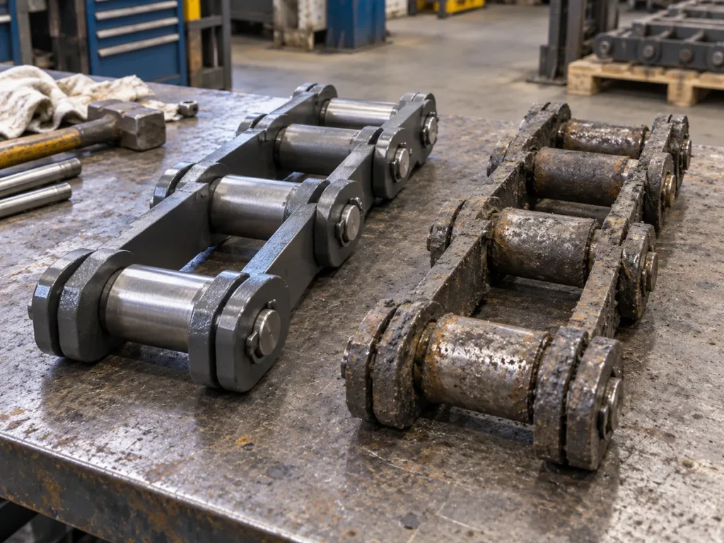
How to Record Model and Component Markings on a Feeder Breaker Chain
Record feeder breaker chain model and component markings with readable close-ups, location context, orientation, conflicts, drawing links, and confidence.
Engineering GuideUpdated Сентябрь 16, 2026
Model and component markings can save hours during feeder breaker chain identification, but they can also mislead a replacement enquiry when their context is lost. A stamped number may identify a component rather than the complete chain. A paint mark may be a maintenance code. A tag may belong to the machine, not the chain. A loose spare may carry a valid model number that has never been installed on the machine being reviewed.
A reliable identification record should include two images and one written note for every important marking: a readable close-up, a wider location view, and a note describing what physical part carries the mark. Then compare the claimed identity with pitch, unit length, scraper width, repeating pattern, and component structure. A marking that conflicts with geometry should remain a conflict, not override the measurements automatically.
The K201B/K207B component trees illustrate why part-level codes matter. Their Chain Sections, links, Flight Sections, and tertiary components carry distinct identifiers in the documented structure. Seeing a component code can narrow the review, but it does not prove that every surrounding component belongs to the same original assembly.
Read it
Capture the full marking with scale, focus, and lighting that preserves every character without guessing damaged digits.
Locate it
Take a second photo showing the marked component inside the chain, flight, spare, or machine.
Verify it
Compare the marking with geometry, drawing/BOM context, repair history, and other identifiers before confirming the chain model.
1. Search Marking Locations Systematically
Inspect accessible link plates, scraper heads/plates, attachment links, extended pins or special components, tags, removed sections, old spares, machine nameplates, and maintenance labels. Do not assume the first readable number is the chain model.
Create a list of every identifier found and give each one a photo ID. This is especially useful on old equipment where multiple supplier and maintenance markings may coexist.
2. Photograph the Marking for Character Accuracy
Use a close view with the camera square to the marked surface when possible. Use side lighting for shallow stamps and multiple angles if corrosion or wear hides characters. Do not digitally reconstruct an unreadable digit and present it as fact; record uncertain characters with a placeholder such as “K20?B.”
Include a scale or known feature when the size of the mark may help distinguish a casting mark from a hand stamp, but do not cover the characters. Preserve the original image before enhancement or annotation.
3. Prove Where the Marking Is Located
Step back and photograph the whole component with the marked area still recognizable. Then take a wider view tying the component to the chain location or spare-part container. This context answers whether the code belongs to a Chain Section, Flight Section, scraper part, machine bracket, or loose component.
Use filenames or the inspection sheet to link close and wide images as a pair. A close-up without context can become detached from its physical meaning as soon as the files are forwarded.
4. Distinguish Model, Component, Drawing, and Maintenance Codes
Compare the format and location with available drawings or parts lists. A code that matches a tertiary component identifier should not be entered into the “chain model” field. A maintenance team may also use its own asset or repair codes; store those as internal markings.
If the meaning remains uncertain, label the marking “unclassified” and keep it in the evidence set. Classification can be resolved later without losing the original observation.
5. Cross-Check the Marking Against Physical Geometry
A marking claiming K201B should be checked against the documented 3 1/2 inch pitch, 21 inch repeating unit, 44 2/5 inch scraper width, and K201B component pattern. A K207B claim should be checked against its 3 1/2 inch pitch, 21 inch unit, 46 inch width, and structural clues such as Scraper Outer Link and Extended Pin.
If the code and geometry disagree, preserve both. Possible explanations include a replaced component, field repair, mixed chain sections, incorrect historical label, or a different interpretation of the marking. Geometry should not be edited to rescue the code.
Marking evidence record
Field
Record
Interpretation control
Marking text
Every readable character plus uncertain characters
Do not guess missing digits.
Physical carrier
Plate, pin, scraper head, tag, machine, spare
Prevents component code from becoming model code.
Location
Machine/strand/unit/flight or spare ID
Maintains traceability.
Close photo
Readable characters
Supports transcription.
Context photo
Whole component and chain/machine relationship
Proves what the mark belongs to.
Geometry check
Pitch, unit, width, component pattern
Tests whether identity and physical configuration agree.
Document cross-reference
Drawing/BOM/old order + revision
Connects code to controlled history.
Status
Unclassified / candidate / confirmed / conflict
Makes uncertainty explicit.
Record rule
A marking can support model identification only when its location and the surrounding geometry are consistent with the claimed configuration.
6. Record Markings on Repaired and Mixed Sections Separately
When a chain has been repaired, one component code may legitimately differ from the rest of the assembly. Map the marked component to the repeating-unit or flight ID and note the repair history if known. Do not generalize the code to the entire chain.
A useful example is a replacement Flight Section installed into an older chain. Its component identifier may be correct for that flight while the surrounding chain belongs to another approved configuration. The RFQ must understand the assembled system, not just the newest marked part.
7. Link Markings to Controlled Documents
Where a marking matches a drawing, bill of material, old quotation, or purchase record, cite that document inside the internal engineering record with revision/date. Confirm that the document belongs to the same machine and assembly. A code found in a general catalogue is weaker evidence than a code tied to the approved order for the installed asset.
If an old record uses a different code for apparently similar geometry, add it as a cross-reference and request engineering review rather than deleting one identity.
8. Build a Confidence Status for Each Identifier
Use statuses such as readable/unclassified, component code confirmed, model candidate, model confirmed, or conflicts with geometry. State the evidence supporting the status. This prevents a marking from gaining false authority simply because it has been copied through several maintenance reports.
When purchasing receives the RFQ, it should be able to see which code is safe to put on the commercial line item and which codes are only supporting evidence.
Model marking
An identifier supported as referring to the complete chain or defined chain configuration.
Component marking
An identifier that refers to one part or subassembly and should not automatically be promoted to model level.
Context image
A wider photograph proving where a close-up marking is physically located.
Confidence status
A controlled label describing how strongly the marking supports the final identification.
9. Preserve Markings Before Cleaning, Blasting, or Disposal
Photograph all identifiers before aggressive cleaning, repainting, blasting, machining, or scrap disposal. If a removed sample is being cleaned for measurement, retain the as-found marking images and sample ID.
Marking preservation is inexpensive insurance. Once the character surface is altered, the team may lose the only direct link to an old component or drawing reference.
Practical Handoff Checklist
Use this handoff checklist to close the field record for How to Record Model and Component Markings on a Feeder Breaker Chain. The goal is not to create another generic maintenance form. It is to preserve the specific observations, reference points and machine context that the next reviewer needs in order to understand how the result was obtained. Keep machine-specific acceptance limits under the approved drawing, maintenance procedure or engineering instruction rather than inventing a universal web value.
Checkpoint
What to record
How the record is used
Search Marking Locations Systematically
Record the exact machine location, strand or side, current operating/shutdown state, and the observation that relates to search marking locations systematically. Include a photograph that lets another reviewer find the same area.
Establishes the context so later measurements are not detached from the machine and chain position.
Photograph the Marking for Character Accuracy
Capture the physical reference used for photograph the marking for character accuracy. Keep the raw dimension, image or marking beside the interpretation, and note any wear, repair, build-up or access limitation that could affect the reading.
Makes the result repeatable and prevents a damaged or poorly defined reference from becoming the replacement requirement.
Prove Where the Marking Is Located
Cross-check prove where the marking is located against any controlled drawing, previous purchase reference or retained spare that is available. Keep current field data and historical information in separate fields when they differ.
Preserves traceability when field condition, historical records and nominal product information do not agree perfectly.
Distinguish Model, Component, Drawing, and Maintenance Codes
For distinguish model, component, drawing, and maintenance codes, state what is confirmed, what is only observed, and what still needs engineering confirmation. Attach the image or measurement that supports the statement rather than relying on a product name alone.
Gives maintenance, purchasing and the supplier a clear list of what can be acted on now and what must be resolved before release.
Separate as-found condition from required replacement geometry. A worn, repaired, dirty or partially dismantled component may still be very useful for identification, but its current shape is not automatically the manufacturing requirement. Label field measurements as observed data, retain the original unit and measurement method, and identify any feature that may have been altered by service. For feeder breaker chain model markings, photographs should show the measurement endpoints or component relationship clearly enough that a remote reviewer can reproduce the logic.
Resolve conflicting information instead of hiding it. If a drawing, old order, marking and current measurement point in different directions, keep each source visible and describe the conflict. Do not average values or silently choose the most convenient one. Use additional photographs, measurements from another intact repeating unit, machine interface information and the controlled document revision to determine which value governs. If preserve markings before cleaning, blasting, or disposal cannot be confirmed during the shutdown, state that limitation explicitly so the open question survives the handoff.
Make the next action obvious for How to Record Model and Component Markings on a Feeder Breaker Chain. The completed record should tell maintenance what should be rechecked, tell purchasing what information belongs in the RFQ, and tell engineering which dimensions or interfaces still need approval. Before the machine returns to service, confirm that the file set includes an overall machine view, a complete repeating chain/flight view, close-ups of relevant components or markings, and the dimensions used in this guide. For feeder breaker chain model markings, a traceable set of observations is more useful than a long narrative with no datum, and it reduces the risk that a replacement decision is made from pitch, appearance or an old part number alone.
Field Decision Notes for This Task
The inspection record for How to Record Model and Component Markings on a Feeder Breaker Chain should be easy to use after the shutdown is over. The following three notes convert the article into a practical handoff without creating a machine-specific acceptance limit. They are especially useful when maintenance observations must be reviewed later by engineering or purchasing and the original chain is no longer accessible.
Confirm Search Marking Locations Systematically
Start by identifying where and how the observation was made. Record the machine, chain side or strand, repeating unit or flight location, and the state of the chain when the check was performed. If the component was dirty, loaded, slack, removed, repaired or visibly deformed, keep that condition beside the reading. A photograph should include enough surrounding structure to let another person find the same location. For this article, the aim is to preserve the context behind search marking locations systematically rather than to reduce it to an isolated number.
Cross-check Photograph the Marking for Character Accuracy
Use a second observation or controlled reference to challenge the first result. That may be a neighbouring intact repeating unit, another chain strand, a drawing revision, an earlier purchase record, or a retained spare part. Keep the original field value visible even when the comparison suggests a different nominal requirement. When the two do not agree, describe why the difference may exist and identify what must be confirmed next. This is particularly important for photograph the marking for character accuracy, because service wear, measurement method and prior repair can affect the as-found condition.
Prepare Prove Where the Marking Is Located for review
Package the result so it can be checked remotely. Include the raw measurement or observation, its unit, reference faces or endpoints, at least one close photograph and one context photograph, and any drawing or marking used during identification. State whether the item is confirmed, candidate or unknown. If prove where the marking is located depends on an assumption, write the open question in the RFQ instead of converting the assumption into a specification. The receiving reviewer should be able to understand the chain condition without reconstructing the method from memory.
Keep the decision boundary visible. Distinguish Model, Component, Drawing, and Maintenance Codes may influence the next maintenance or sourcing step, but the website does not set a universal discard, tension or interchangeability limit. Use the equipment procedure, approved drawing and order-specific engineering requirements for acceptance decisions. The purpose of this record is to make the observation behind feeder breaker chain model markings traceable enough that the correct product or engineering route can be chosen without guessing.
Questions to Resolve Before the Next Decision
Can a stamped K201B or K207B code confirm the whole chain?
It is strong evidence only when the code clearly belongs to the relevant assembly and the pitch, unit length, width, component pattern, and machine context do not conflict.
What if one digit is unreadable?
Record the uncertainty rather than guessing. Use multiple lighting angles, old drawings, component geometry, and other markings to narrow the identity.
Should maintenance paint marks be removed before photographing?
Photograph the as-found condition first. Cleaning should follow the approved procedure and should not destroy markings or other evidence.
What if different chain sections have different codes?
Map each code to its location and investigate repair or mixed-section history. Do not assume the newest or clearest code represents the entire chain.
Next Step: Close the Technical Record
Markings are valuable because they can connect a physical chain to a model, component, drawing, or maintenance history. Their weakness is that a number without context is easy to misclassify.
Always preserve the text, the carrier component, the chain/machine location, geometry comparison, and document cross-reference. When those layers agree, the marking becomes strong identification evidence; when they conflict, the conflict becomes the next engineering question.