What Photos Should You Send for a Feeder Breaker Chain RFQ?
Build a feeder breaker chain RFQ photo set that shows machine context, repeating geometry, components, markings, dimensions, and damage clearly.
Engineering GuideUpdated Tháng 9 16, 2026
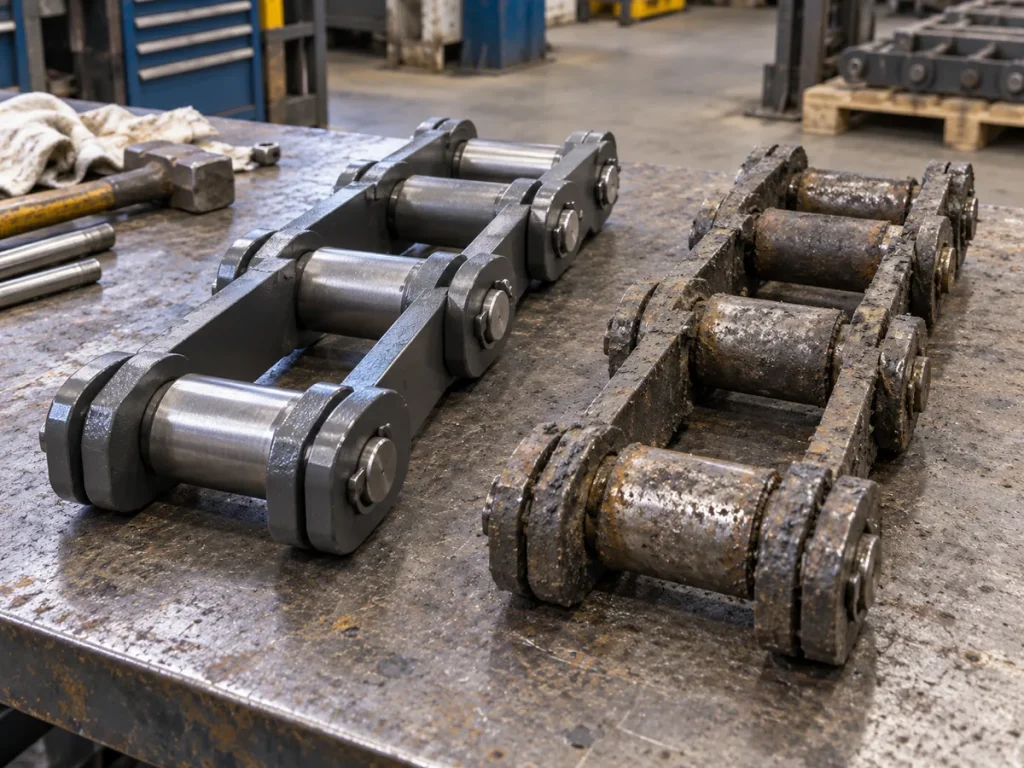
Photos can shorten a feeder breaker chain identification cycle, but only when they answer engineering questions rather than simply prove that a chain exists. A close-up of a broken scraper with no view of the surrounding assembly can be dramatic and still be nearly useless for replacement sourcing. Conversely, an organized set of eight or ten ordinary photographs can show where the chain runs, how the repeating unit is assembled, which side is damaged, what dimensions were measured, and whether a model marking is actually attached to the chain in question.
The goal is not to create a professional product photo shoot. The goal is to preserve evidence before the machine is closed, the chain is removed, or a temporary repair changes the geometry. That means taking photographs in a planned sequence: context first, then the complete repeating unit, then the joints and flight assembly, then dimensions and markings, and finally the defect or uncertainty that triggered the RFQ.
For an underground feeder breaker, all photography must stay inside the site’s isolation and access rules. Do not step into a hazardous zone or defeat guarding for a better camera angle. If a critical view cannot be taken safely, note the missing view and supply the drawing, maintenance record, or removed sample instead.
Context
Show the feeder breaker, chain path, strand/side, and where the photographed unit sits in the machine.
Geometry
Capture an intact repeating unit, flight arrangement, joint details, and measurement endpoints before focusing on damage.
Traceability
Name images consistently and link each photo to the model claim, dimension, marking, or open question it supports.
1. Start with One Photograph That Answers “Where Is This?”
Begin with a wide view that places the chain inside the feeder breaker or chain conveyor. The reviewer should be able to see the machine context, travel direction if known, the chain strand or side, and enough surrounding structure to understand the relationship between the chain and the conveyor. This is not the image for reading a pin or measuring a flight; it is the orientation image that prevents every later close-up from becoming an isolated puzzle.
If the enquiry involves two strands, photograph both and label them separately. If one side has been repaired, adjusted, or replaced at a different time, say so. Context photographs are especially valuable when the same plant handles shuttle-car, bolter-miner, reclaim-feeder, and feeder-breaker chains because a similar-looking link can otherwise be routed to the wrong application family.
2. Photograph One Complete Repeating Unit Before Individual Components
Move closer and capture a complete intact repeating pattern. For the listed K201B and K207B feeder breaker scraper chains, the repeating unit is described as one Flight Section and two Chain Sections. A useful image therefore needs enough length to show that relationship rather than cropping tightly around a single link. If the installed chain is different, the photograph should reveal that difference instead of being framed to resemble a known listed model.
Shoot the repeating unit as square to the chain plane as practical so perspective does not distort width and spacing. Take a second oblique view if it helps show how the flight attaches to the two strands. The two images serve different purposes: one preserves plan geometry, while the other helps the reviewer understand depth, attachment faces, and the relationship between pins, links, and the scraper assembly.
3. Build a Component Close-Up Set
After the complete unit is documented, move to the joints and attachments. Photograph outer and inner link areas, visible pin and bush locations, flight or scraper connections, retention features, and any special attachment link that appears different from the standard chain section. Keep at least one adjacent component in frame so the reviewer can orient the close-up.
The component tree can contain useful identification clues. K201B documents an Outer Link, Inner Link, Chain Section, Flight Section, Locating Bush, Spring Pin, Scraper Head, and Scraper Plate. K207B documents those general kinds of parts but also includes a Scraper Outer Link, Extended Pin, and T-Pin. A close-up that shows those features can be more discriminating than a photograph of the whole chain from several metres away.
4. Photograph Every Important Dimension with Its Endpoints Visible
When a photograph supports a measurement, show both the measuring tool and the physical endpoints. For pitch, the image should make the equivalent joint references visible. For scraper width, show the two edges or reference faces used. For unit length or flight spacing, include enough of the repeating pattern that the start and finish are unambiguous. A number typed into an email without endpoint evidence is much harder to audit.
Do not rely on the photograph alone for the value. Record the dimension in the RFQ worksheet and use the photo as supporting evidence. If the reading is difficult because the chain is worn, dirty, bent, or partly hidden, photograph the condition and state that the measurement is approximate. Engineering can work with qualified evidence; it cannot reliably work with false precision.
Minimum RFQ photo set and the question each view should answer
Which machine and chain location are we reviewing?
Complete repeating unit
At least one intact flight-and-chain pattern
What assembly pattern is actually installed?
Joint close-up
Link, pin/bush area, retention and adjacent link
How is the chain joint configured?
Flight connection
Scraper/flight attachment and nearby chain section
How does the conveying element attach to the chain?
Dimension view
Tool plus visible start and end references
What exactly was measured?
Marking view
Close-up plus location context
Does the marking belong to this chain or machine?
Damage comparison
Defect plus comparable intact area
Is the feature local damage or normal geometry?
Record rule
If a required view cannot be obtained safely, mark it as missing and replace the evidence with an approved drawing, record, or removed sample rather than taking a hazardous photograph.
If the chain, flight, tag, machine plate, or old spare carries a model or component marking, take a sharp close-up and a wider image that shows where the marking is located. This prevents a common traceability failure: a perfectly readable part number is photographed, but no one can later prove whether it belonged to the installed chain, a nearby spare, or another machine.
Use oblique lighting when stamped characters are shallow. Wipe only as permitted by the maintenance procedure and avoid aggressive cleaning that could remove paint marks, field identification, or failure evidence. If several markings conflict, keep all of them. Do not choose the one that best matches the desired replacement and discard the others from the record.
Context photo
A wider image that proves where the detailed images were taken.
Repeating-unit photo
A view long enough to show the recurring relationship between chain sections and the flight/scraper assembly.
Measurement evidence
A photograph that visibly connects a recorded number to two defined physical endpoints.
Traceable marking
A readable identifier supported by a second view showing where that identifier is physically located.
6. Document Damage with a Healthy Comparison Area
For a broken, bent, cracked, worn, or heavily polished part, take one close image of the affected surface and one comparison image of a nearby intact component with the same function. Add a wider view that places the defect in the repeating unit. The three-view sequence distinguishes local damage from a design feature and helps the reviewer judge whether the surrounding chain needs broader inspection.
Do not use photographs to declare a universal reject condition. Uneven flight wear, pin/bush condition, abnormal side contact, or sprocket interaction may justify engineering review, but the acceptance decision belongs to the approved machine, chain, and site criteria. The RFQ photo set should faithfully show the condition and let the controlled specification determine the disposition.
7. Name and Sequence the Files So the RFQ Can Be Reviewed Remotely
Use filenames that carry meaning outside the messaging app where the images were first sent. A simple sequence such as FB01-overall-left-strand, FB02-complete-unit, FB03-flight-connection, FB04-pitch-measurement, and FB05-marking is easier to review than five files named IMG_4821 through IMG_4825. If the RFQ covers several machines, put the equipment identifier at the start of each filename.
Keep a short photo index in the RFQ worksheet. For each image, state what it is intended to prove: machine context, repeating unit, scraper width, marking, damaged bush area, or another point. That index transforms the photo folder into an engineering evidence package and allows follow-up questions to reference a specific image rather than “the third photo you sent yesterday.”
8. Know When Photos Are Not Enough
Photography is strongest when it is combined with dimensions and controlled documents. If the installed chain has been modified, if measurement endpoints cannot be identified, if the drawing and field assembly conflict, or if the chain is too damaged to reconstruct the repeating pattern, add a measured sketch, old purchase record, approved drawing, or safely removed sample. A supplier should not be forced to infer hidden geometry from a camera angle.
The same applies when a known model is claimed but key evidence disagrees. If an enquiry says K201B while the measured scraper width is closer to another configuration, preserve both facts and request engineering review. The correct RFQ outcome may be “model not yet confirmed,” which is safer than ordering a nominally similar chain on incomplete visual evidence.
Use this handoff checklist to close the field record for What Photos Should You Send for a Feeder Breaker Chain RFQ?. The goal is not to create another generic maintenance form. It is to preserve the specific observations, reference points and machine context that the next reviewer needs in order to understand how the result was obtained. Keep machine-specific acceptance limits under the approved drawing, maintenance procedure or engineering instruction rather than inventing a universal web value.
Checkpoint
What to record
How the record is used
Start with One Photograph That Answers “Where Is This?”
Record the exact machine location, strand or side, current operating/shutdown state, and the observation that relates to start with one photograph that answers “where is this?”. Include a photograph that lets another reviewer find the same area.
Establishes the context so later measurements are not detached from the machine and chain position.
Photograph One Complete Repeating Unit Before Individual Components
Capture the physical reference used for photograph one complete repeating unit before individual components. Keep the raw dimension, image or marking beside the interpretation, and note any wear, repair, build-up or access limitation that could affect the reading.
Makes the result repeatable and prevents a damaged or poorly defined reference from becoming the replacement requirement.
Build a Component Close-Up Set
Cross-check build a component close-up set against any controlled drawing, previous purchase reference or retained spare that is available. Keep current field data and historical information in separate fields when they differ.
Preserves traceability when field condition, historical records and nominal product information do not agree perfectly.
Photograph Every Important Dimension with Its Endpoints Visible
For photograph every important dimension with its endpoints visible, state what is confirmed, what is only observed, and what still needs engineering confirmation. Attach the image or measurement that supports the statement rather than relying on a product name alone.
Gives maintenance, purchasing and the supplier a clear list of what can be acted on now and what must be resolved before release.
Separate as-found condition from required replacement geometry. A worn, repaired, dirty or partially dismantled component may still be very useful for identification, but its current shape is not automatically the manufacturing requirement. Label field measurements as observed data, retain the original unit and measurement method, and identify any feature that may have been altered by service. For feeder breaker chain RFQ photos, photographs should show the measurement endpoints or component relationship clearly enough that a remote reviewer can reproduce the logic.
Resolve conflicting information instead of hiding it. If a drawing, old order, marking and current measurement point in different directions, keep each source visible and describe the conflict. Do not average values or silently choose the most convenient one. Use additional photographs, measurements from another intact repeating unit, machine interface information and the controlled document revision to determine which value governs. If know when photos are not enough cannot be confirmed during the shutdown, state that limitation explicitly so the open question survives the handoff.
Make the next action obvious for What Photos Should You Send for a Feeder Breaker Chain RFQ?. The completed record should tell maintenance what should be rechecked, tell purchasing what information belongs in the RFQ, and tell engineering which dimensions or interfaces still need approval. Before the machine returns to service, confirm that the file set includes an overall machine view, a complete repeating chain/flight view, close-ups of relevant components or markings, and the dimensions used in this guide. For feeder breaker chain RFQ photos, a traceable set of observations is more useful than a long narrative with no datum, and it reduces the risk that a replacement decision is made from pitch, appearance or an old part number alone.
Questions to Resolve Before the Next Decision
How many photos should I send?
There is no fixed magic number. Send enough images to cover machine context, one complete repeating unit, joints and attachments, critical dimensions, markings, and the condition that triggered the enquiry. Eight well-planned views can be more useful than fifty unrelated close-ups.
Should the measuring tape be visible in every photo?
Only in the images intended to support a dimension. Keep separate clean geometry photographs as well, because a tape can hide edges, holes, pins, or attachment details that engineering needs to see.
What if the chain is covered with material?
Photograph the as-found condition first. Clean only under the approved site procedure, then take a second set if the geometry becomes visible. Label both conditions so the later reviewer knows which image preceded cleaning.
Can a photo of a part number confirm the model?
A marking is strong evidence only when its location and relationship to the installed chain are clear and the rest of the geometry does not conflict. Pair the close-up with a wider location photo and dimensional evidence.
Next Step: Close the Technical Record
A useful feeder breaker chain RFQ photo set tells a story in a controlled order: where the chain is installed, what the repeating assembly looks like, how the joints and flights are configured, what was measured, which markings are present, and what abnormal condition prompted the enquiry. That structure lets a remote reviewer ask precise questions instead of requesting another round of random images.
Before the shutdown ends, open the photo folder beside the RFQ sheet and check whether each important dimension or model claim has visible support. If the chain still cannot be identified with confidence, say so and send the evidence as an engineering review package rather than forcing a model selection.