How Chain and Sprocket Wear Affect Feeder Breaker Replacement Planning
Plan feeder breaker chain replacement with sprocket inspection, engagement evidence, alignment observations, wear history, and coordinated shutdown.
Engineering GuideUpdated செப்டம்பர் 16, 2026
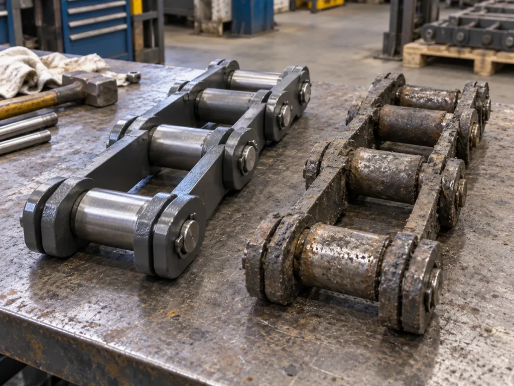
Feeder breaker chain replacement is often triggered by visible chain condition: damaged flights, repeated take-up adjustment, joint wear, broken retention, or a planned service interval in the machine maintenance program. Yet the chain does not operate alone. Every pitch engages the sprocket, every flight follows the chain path, and any misalignment or tooth wear can influence how the replacement assembly loads and tracks.
General conveyor-chain engineering practice therefore treats chain and sprocket condition as related evidence. A worn chain can alter engagement; a worn or misaligned sprocket can accelerate abnormal contact on a new chain. The exact acceptance criteria, wear limits, and replacement thresholds must come from the controlled feeder breaker and chain documentation. This article focuses on how to inspect and plan the two components together without importing an unrelated numeric discard rule.
The planning objective is to enter the shutdown with enough evidence to decide whether the scope is chain only, sprocket work, alignment correction, take-up repair, flight or guide work, or a coordinated replacement. That reduces the risk of installing a correct new chain into an unresolved machine condition.
Inspect together
Photograph chain joints, flights, and sprocket tooth spaces during the same shutdown and note their relative location.
Separate symptoms from causes
Chain elongation, tooth wear, side scoring, and tracking are observations; use alignment and engagement checks before assigning cause.
Plan the interface
Replacement scope should include fit, engagement, alignment, take-up range, and controlled restart checks, not only a chain part number.
1. Understand Why Wear at Chain Joints Changes Sprocket Engagement
Articulated chain joints work through pins and bushes or equivalent bearing surfaces. As those surfaces wear, the effective distance through a sequence of joints can change. The chain may then seat differently as it approaches the sprocket. A repeatable multi-pitch measurement can help document that trend, but the final service limit remains specification dependent.
During replacement planning, record the chain measurement and the sprocket condition at the same time. If the chain shows a strong length-change trend and the sprocket shows unusual engagement or tooth wear, engineering can review the pair instead of assuming one component alone explains the behavior.
2. Inspect Sprocket Tooth Spaces for Pattern, Not Just Depth
Clean enough of the accessible tooth profile under the approved procedure to see where the chain has been contacting. Look for consistent polished areas, asymmetric side wear, hooking or profile change, impact marks, and tooth-to-tooth variation. Photograph several consecutive teeth rather than choosing only the worst-looking tooth.
Do not convert a visual impression into a universal wear percentage. The important planning question is whether the tooth profile and contact pattern remain suitable under the machine specification and whether the wear pattern suggests alignment, engagement, or contamination issues that should be corrected before a new chain is installed.
3. Compare Left and Right Sprocket Evidence on Paired Systems
Where two strands use paired sprockets, compare corresponding sides. Differences in side scoring, tooth wear, chain seating, or take-up history can reveal an asymmetric system condition. Record which sprocket belongs to which chain strand so a later reviewer can connect tooth evidence with chain measurements and flight alignment.
If one side has a different replacement history, note it. Mixing a newer sprocket with an older worn component may create a different engagement history from the opposite side. The replacement plan should work from the actual installed condition rather than assuming both sides have aged equally.
4. Check Alignment and Tracking Evidence Before Installing New Parts
Abnormal side wear on links or sprocket teeth, flights that run skewed, repeated guide contact, or a chain that consistently tracks toward one side are reasons to inspect shaft, sprocket, and track alignment under the machine procedure. These symptoms do not automatically prove misalignment, but they justify checking it.
If the shutdown includes sprocket replacement, preserve the old sprocket photographs before removal and record shim, shaft, hub, or mounting observations relevant to alignment. A new chain and new sprocket can still wear poorly if the underlying geometry is not corrected.
5. Include Take-Up Range and Adjustment History in the Replacement Decision
A chain near the end of available take-up range may have a very different maintenance risk from one with substantial controlled adjustment remaining, but the meaning of the position is machine specific. Record the actual take-up positions and the history of recent changes. If one side has consumed more range, keep that asymmetry visible.
Replacement planning should also consider what the take-up will need after new components are installed. The machine procedure should define reset and initial adjustment. Do not fabricate a web-based starting position; make the required setup value part of the shutdown work pack.
6. Inspect Flight and Chain Damage for Engagement Clues
Bent flights, uneven scraper wear, damaged attachment links, polished plate sides, or repeated pin/retention problems can be downstream evidence of how the chain has been running. Map those findings to chain location and, where possible, to the corresponding sprocket or path area.
For K201B/K207B replacement review, keep model-specific configuration evidence separate from wear evidence. A worn scraper width should not be used as the nominal replacement width, and a damaged attachment should not be assumed to represent the original component geometry.
7. Decide Whether Chain and Sprocket Work Should Be Coordinated
The correct scope depends on the controlled inspection criteria, available downtime, component condition, and risk of leaving a worn interface in service. The planning team should explicitly decide whether the sprockets will remain, be repaired under an approved method, or be replaced, and document the evidence supporting that decision.
Avoid a procurement process where chain and sprocket decisions happen in separate departments with no shared inspection record. A coordinated package can include chain model/dimensions, sprocket drawings or measurements, tooth-condition photos, shaft/interface details, and alignment findings.
Chain-and-sprocket replacement planning matrix
Evidence
Chain question
Sprocket/system question
Multi-pitch measurement
Is effective chain length changing consistently?
Does engagement show climbing, impact, or uneven seating?
Side wear
Are plates or pins showing asymmetric contact?
Are tooth sides, shaft alignment, or guides showing the same side bias?
Flight condition
Are flights skewed, bent, or unevenly worn?
Is the paired sprocket/track relationship consistent across strands?
Take-up history
How much and how often has adjustment changed?
Does the take-up mechanism hold and move evenly?
Repair history
Are mixed sections or repaired attachments present?
Did symptoms begin after sprocket or machine-side work?
Incoming parts
Does chain match approved configuration?
Does sprocket match approved tooth/interface drawing?
Record rule
Use the controlled machine and chain criteria for disposition; the matrix ensures the chain and engaging system are reviewed together.
8. Plan the New-Component Verification Before the Shutdown Starts
Before installation, confirm that the supplied chain matches the approved pitch, repeating unit, scraper width, component arrangement, and drawing. Confirm the sprocket part or drawing independently. Then define the checks that will be performed after installation: alignment, seating, clearances, take-up setup, flight tracking, retention, and controlled initial operation.
This preplanned verification matters because a shutdown is the worst time to discover that the incoming chain and sprocket were specified from different revisions. Put the chain drawing, sprocket drawing, inspection report, and purchase order in the same work pack.
Engagement
The way chain joints or bushings enter, seat in, and leave the sprocket tooth spaces.
Wear pattern
The location and shape of material loss or polished contact used as evidence of how components interact.
Coordinated replacement
A shutdown scope in which chain, sprocket, alignment, take-up, and restart verification are planned together.
Baseline
The first controlled condition and measurement record after approved new components are installed.
9. Use Post-Installation Observation to Close the Replacement Record
After the controlled restart, observe chain entry and exit at sprockets, flight tracking, side contact, unusual impact, and take-up behavior from approved safe positions. Compare the observations with the pre-replacement symptoms. Record whether the original issue was resolved rather than assuming new parts guarantee a correct system.
Schedule follow-up checks under the machine maintenance plan and preserve the same reference locations. The first post-replacement measurements become the baseline for future trend comparison.
Practical Handoff Checklist
Use this handoff checklist to close the field record for How Chain and Sprocket Wear Affect Feeder Breaker Replacement Planning. The goal is not to create another generic maintenance form. It is to preserve the specific observations, reference points and machine context that the next reviewer needs in order to understand how the result was obtained. Keep machine-specific acceptance limits under the approved drawing, maintenance procedure or engineering instruction rather than inventing a universal web value.
Checkpoint
What to record
How the record is used
Understand Why Wear at Chain Joints Changes Sprocket Engagement
Record the exact machine location, strand or side, current operating/shutdown state, and the observation that relates to understand why wear at chain joints changes sprocket engagement. Include a photograph that lets another reviewer find the same area.
Establishes the context so later measurements are not detached from the machine and chain position.
Inspect Sprocket Tooth Spaces for Pattern, Not Just Depth
Capture the physical reference used for inspect sprocket tooth spaces for pattern, not just depth. Keep the raw dimension, image or marking beside the interpretation, and note any wear, repair, build-up or access limitation that could affect the reading.
Makes the result repeatable and prevents a damaged or poorly defined reference from becoming the replacement requirement.
Compare Left and Right Sprocket Evidence on Paired Systems
Cross-check compare left and right sprocket evidence on paired systems against any controlled drawing, previous purchase reference or retained spare that is available. Keep current field data and historical information in separate fields when they differ.
Preserves traceability when field condition, historical records and nominal product information do not agree perfectly.
Check Alignment and Tracking Evidence Before Installing New Parts
For check alignment and tracking evidence before installing new parts, state what is confirmed, what is only observed, and what still needs engineering confirmation. Attach the image or measurement that supports the statement rather than relying on a product name alone.
Gives maintenance, purchasing and the supplier a clear list of what can be acted on now and what must be resolved before release.
Separate as-found condition from required replacement geometry. A worn, repaired, dirty or partially dismantled component may still be very useful for identification, but its current shape is not automatically the manufacturing requirement. Label field measurements as observed data, retain the original unit and measurement method, and identify any feature that may have been altered by service. For feeder breaker chain sprocket wear, photographs should show the measurement endpoints or component relationship clearly enough that a remote reviewer can reproduce the logic.
Resolve conflicting information instead of hiding it. If a drawing, old order, marking and current measurement point in different directions, keep each source visible and describe the conflict. Do not average values or silently choose the most convenient one. Use additional photographs, measurements from another intact repeating unit, machine interface information and the controlled document revision to determine which value governs. If use post-installation observation to close the replacement record cannot be confirmed during the shutdown, state that limitation explicitly so the open question survives the handoff.
Make the next action obvious for How Chain and Sprocket Wear Affect Feeder Breaker Replacement Planning. The completed record should tell maintenance what should be rechecked, tell purchasing what information belongs in the RFQ, and tell engineering which dimensions or interfaces still need approval. Before the machine returns to service, confirm that the file set includes an overall machine view, a complete repeating chain/flight view, close-ups of relevant components or markings, and the dimensions used in this guide. For feeder breaker chain sprocket wear, a traceable set of observations is more useful than a long narrative with no datum, and it reduces the risk that a replacement decision is made from pitch, appearance or an old part number alone.
Field Decision Notes for This Task
The inspection record for How Chain and Sprocket Wear Affect Feeder Breaker Replacement Planning should be easy to use after the shutdown is over. The following three notes convert the article into a practical handoff without creating a machine-specific acceptance limit. They are especially useful when maintenance observations must be reviewed later by engineering or purchasing and the original chain is no longer accessible.
Confirm Understand Why Wear at Chain Joints Changes Sprocket Engagement
Start by identifying where and how the observation was made. Record the machine, chain side or strand, repeating unit or flight location, and the state of the chain when the check was performed. If the component was dirty, loaded, slack, removed, repaired or visibly deformed, keep that condition beside the reading. A photograph should include enough surrounding structure to let another person find the same location. For this article, the aim is to preserve the context behind understand why wear at chain joints changes sprocket engagement rather than to reduce it to an isolated number.
Cross-check Inspect Sprocket Tooth Spaces for Pattern, Not Just Depth
Use a second observation or controlled reference to challenge the first result. That may be a neighbouring intact repeating unit, another chain strand, a drawing revision, an earlier purchase record, or a retained spare part. Keep the original field value visible even when the comparison suggests a different nominal requirement. When the two do not agree, describe why the difference may exist and identify what must be confirmed next. This is particularly important for inspect sprocket tooth spaces for pattern, not just depth, because service wear, measurement method and prior repair can affect the as-found condition.
Prepare Compare Left and Right Sprocket Evidence on Paired Systems for review
Package the result so it can be checked remotely. Include the raw measurement or observation, its unit, reference faces or endpoints, at least one close photograph and one context photograph, and any drawing or marking used during identification. State whether the item is confirmed, candidate or unknown. If compare left and right sprocket evidence on paired systems depends on an assumption, write the open question in the RFQ instead of converting the assumption into a specification. The receiving reviewer should be able to understand the chain condition without reconstructing the method from memory.
Keep the decision boundary visible. Check Alignment and Tracking Evidence Before Installing New Parts may influence the next maintenance or sourcing step, but the website does not set a universal discard, tension or interchangeability limit. Use the equipment procedure, approved drawing and order-specific engineering requirements for acceptance decisions. The purpose of this record is to make the observation behind feeder breaker chain sprocket wear traceable enough that the correct product or engineering route can be chosen without guessing.
Questions to Resolve Before the Next Decision
Should sprockets always be replaced with the chain?
Not as a universal rule. Inspect the sprocket condition and use the machine/chain criteria to decide. The key is to avoid installing a new chain without reviewing the engagement interface.
Can tooth wear be judged from one photograph?
A photograph is supporting evidence. Inspect several teeth, compare both sides where applicable, and use the controlled profile or acceptance method for disposition.
Why record alignment before replacing parts?
Abnormal alignment can create wear on both chain and sprocket. New parts may repeat the same pattern if the underlying machine geometry remains unresolved.
What should purchasing receive?
A coordinated specification package should identify the chain configuration, sprocket/drawing reference, relevant dimensions, condition evidence, quantity, and any inspection or documentation requirements.
Next Step: Close the Technical Record
Feeder breaker chain and sprocket wear are connected through engagement. Replacement planning should therefore treat chain measurements, tooth condition, alignment evidence, flight behavior, and take-up history as one engineering record.
The controlled specifications decide when each component is repairable or replaceable. The planning workflow decides whether the shutdown will actually solve the system condition instead of swapping one worn part and leaving the interface that shaped its wear untouched.