Removing a feeder breaker chain can destroy the very context needed to identify it. A chain laid out on the floor no longer shows which side faced the sprocket, where a damaged flight sat in the machine, which strand was repeatedly adjusted, or which pins defined the field measurement. If that context is not marked before disassembly, engineering may receive an excellent sample with poor traceability.
The solution is a simple pre-removal marking plan coordinated with the approved maintenance procedure. Establish a master reference, direction of travel, strand/side, repeating-unit identifiers, measurement endpoints, and repair or damage locations. Photograph each mark in place before the chain moves. The marks do not replace drawings or measurements; they preserve the map that makes those records meaningful.
Use only marking methods allowed by the site and component procedure. Do not grind, stamp, drill, weld, or otherwise alter a stressed chain component merely to create an identifier. Paint marker, tag, removable label, or a sketch may be suitable depending on the environment, but the controlled maintenance plan decides what is permissible.
Master datum
Create one unmistakable starting reference tied to a fixed machine location and photograph it in place.
Direction and side
Mark travel direction and left/right or strand identity so the removed chain cannot be reversed in the evidence record.
Measurement anchors
Label the exact joints or flights used for pitch, unit length, width, and spacing records before disassembly changes their posture.
1. Decide the Information That Must Survive Removal
List what the downstream reviewer will need: machine ID, chain side/strand, direction of travel, inlet/discharge orientation, reference flight, pitch-measurement endpoints, unit-length endpoints, flight-spacing endpoints, damaged units, repaired units, and any location associated with abnormal contact or adjustment. This list becomes the marking plan.
Do not mark every link without purpose. Too many marks can be as confusing as none. Use a hierarchy: one master datum, numbered repeating units or selected inspection stations, and targeted marks for dimensions or defects.
2. Establish a Master Reference on the Machine and Chain

Choose a fixed machine feature that will remain after the chain is removed, such as a maintenance datum, accessible frame point, or documented station. Mark the nearest chain flight or unit as the master chain reference and photograph both in one frame. The image should prove their relationship.
Record the master reference in the inspection sheet using words that another person can understand. “Flight 0 at discharge-side frame mark A” is more useful than “start here.” If the machine already has an approved numbering scheme, use it rather than inventing a parallel one.
Related technical page: replacement feeder breaker chain evidence guide.
3. Mark Direction of Travel and Chain Side
Direction matters because wear and attachment orientation can be asymmetric. Place an approved arrow or tag on selected units and write the travel direction in the photo index. For paired chains, mark left/right or the site’s preferred strand identification on both the chain and the evidence sheet.
If there is any chance the removed chains could be mixed, use distinct tag prefixes such as L and R. Do not rely on floor position in the workshop; handling, cleaning, and inspection can reorder the assemblies quickly.
4. Label Repeating Units and Flight Positions

Number flights or repeating units from the master datum at an interval that supports the planned inspection. If the chain has one flight per repeat, the flight number can double as the repeating-unit identity. If the pattern is more complex, use a separate unit number and component suffix.
This sequence allows measurements and defects to be mapped. “Crack at flight F17, left strand” can later be related to “pitch span P16-P20” and to the machine location shown before removal. Without the unit map, those observations become isolated workshop findings.
5. Mark Pitch and Unit-Length Measurement Endpoints Explicitly
Before removal, identify the exact physical features used for each controlled measurement. Use small tags or annotated photographs to name endpoints such as P-A and P-B for a multi-pitch span and U-A/U-B for a repeating unit. Record the number of pitch intervals or units between them.
Once the chain is removed and relaxed, the measured geometry may sit differently. The pre-removal endpoint record allows engineering to distinguish a change in chain posture from a change in measurement method.
Related technical page: feeder breaker chain pitch and dimension guide.
6. Map Damage and Repairs Without Hiding the As-Found Condition
Tag damaged flights, unusual joints, field welds, replaced sections, and obvious retention changes. Photograph them before cleaning or disassembly when safe. If a part will be cut or separated for laboratory inspection, give the removed sample an identifier linked to the original chain location.
Do not mark directly over a crack, wear surface, stamped identifier, or other evidence. Place the tag nearby and use the photo index to connect it to the feature. Preserving the surface may be important for later engineering or failure review.
| Mark | What it identifies | Record with |
|---|---|---|
| M0 | Master chain datum tied to fixed machine reference | Wide context photo and sketch |
| L/R | Strand or side identity | Machine orientation and travel direction |
| F01… | Flight or repeating-unit sequence | Photo index and defect map |
| P-A / P-B | Pitch-span endpoints | Raw span, pitch count, endpoint photos |
| U-A / U-B | Unit-length endpoints | Repeat description and dimension |
| Dxx | Damage or unusual condition | As-found photo and observation |
| Rxx | Known field repair or replacement section | Maintenance history and comparison photo |
| Sxx | Removed sample identity | Parent chain section and original location |
| Record rule | Use only approved non-damaging marking methods and preserve the photographic map before components are moved, cleaned, or separated. | |
7. Photograph the Marking Scheme as a Map
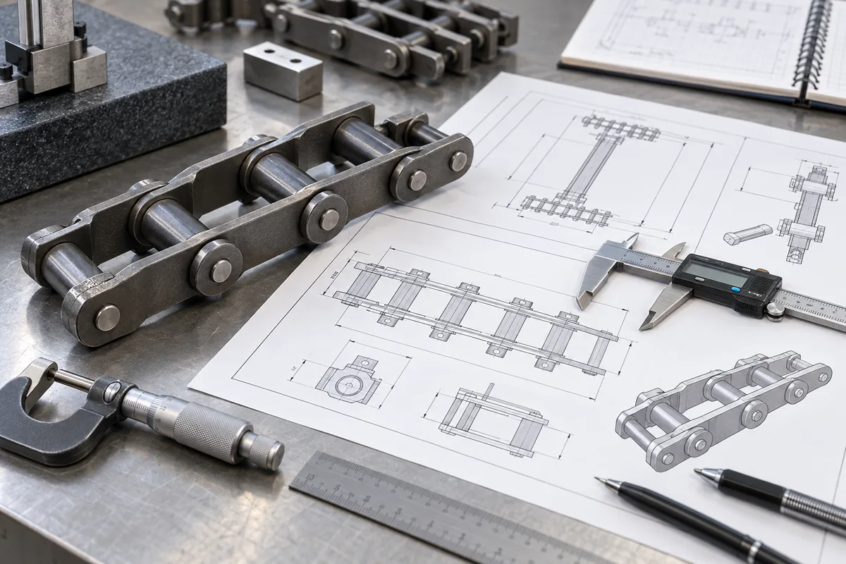
Take a sequence of overlapping photographs along the accessible chain path so the master datum, unit numbers, and special tags can be reconstructed. Add one simple sketch showing travel direction, left/right strands, and the approximate positions of key tags. The sketch does not need to be a production drawing; it needs to preserve relationships.
Store the images and sketch with the measurement sheet before removal begins. A marking system that exists only physically on components can still be lost when parts are cleaned, painted, or discarded.
8. Transfer the Identity to Removed Sections and Samples
As the chain is broken into handling lengths, carry the original identity onto each section. Record the first and last unit IDs in that removed piece and keep left/right and travel direction visible. If a single component is removed from a section, give it a child ID that points back to the chain section.
This chain-of-custody style record is useful even when no formal failure analysis is planned. It prevents a good component from another location becoming the accidental comparison sample for a damaged area and keeps workshop measurements tied to the original machine.
- Master datum
- The primary chain reference tied to a fixed machine location.
- Unit map
- The sequence that connects repeating chain units or flights with their original machine positions.
- Measurement anchor
- A labelled physical feature used as the start or end of a controlled field measurement.
- Sample identity
- A code that preserves the removed component’s relationship to its original chain section and machine location.
9. Reconcile Workshop Measurements with the Pre-Removal Record

After cleaning or disassembly, repeat critical dimensions where appropriate and compare them with the in-machine measurement. A difference does not automatically mean one value is wrong. Chain posture, debris removal, access, and tool position can change the reading. Keep both and explain the measurement state.
If the removed chain is being used for replacement sourcing, the final RFQ should identify which dimensions came from installed-chain measurements and which came from cleaned bench inspection. This distinction prevents later revisions from blending two measurement conditions into one unexplained number.
Related technical page: send pre-removal and bench records for review.
Practical Handoff Checklist
For this task, use this final field-review layer when the inspection record moves from the machine to maintenance, engineering, or purchasing. Apply only the checks that match the current job, and keep machine-specific acceptance limits under the control of the approved drawing or procedure.
For this task, keep these controlled terms explicit when they apply: feeder breaker chain, field evidence, configuration, measurement, engineering review. Using the same labels throughout this specific record helps the next reviewer separate method, physical observation, and pending confirmation without creating an unsupported requirement.
M0 as a field checkpoint. treat this item as a reproducible inspection step rather than a box to tick. Record Master chain datum tied to fixed machine reference with enough context that another technician can identify the same component, datum, machine state, and observation point. Then use that evidence to Wide context photo and sketch. Keep the raw observation beside the interpretation: a photograph, dimension, marking, or condition note should remain visible even if a later engineering review reaches a different conclusion. If the required reference is hidden, damaged, or uncertain, mark the limitation and request the missing drawing, measurement, or machine information instead of substituting a convenient value. This makes the record useful for maintenance, purchasing, and engineering without turning field evidence into an unsupported specification.
Make L/R auditable. A practical test is whether a person who was not present at the shutdown could reconstruct what was checked. Capture Strand or side identity; identify the exact location and reference faces; and note whether the chain was installed, removed, cleaned, loaded, slack, or otherwise in a condition that can affect the observation. The next step is to Machine orientation and travel direction. If two sources disagree, retain both values and describe the conflict rather than averaging them or selecting the one that looks more familiar. That discipline is especially important when a used chain is being compared with a drawing or catalogue, because wear, repair, and measurement method can all change the field result without changing the controlled requirement.
Use F01… to connect inspection with the next decision. the record should show Flight or repeating-unit sequence and should make clear which statement is measured fact, which is historical information, and which still requires confirmation. The evidence is then used to Photo index and defect map. A strong handoff does not ask purchasing or a supplier to infer missing geometry from a product name. It supplies the actual observation and, when the requirement is unknown, asks a specific technical question. This approach also protects repeat inspections: future teams can return to the same datum or component and compare like with like instead of trying to interpret an undocumented method change.
Close the loop on P-A / P-B. do not stop when Pitch-span endpoints has been written down. Review whether the evidence is complete enough to Raw span, pitch count, endpoint photos, whether the photographs show the reference clearly, and whether any value was copied from an old document rather than confirmed on the current machine. Preserve the distinction between as-found condition and required replacement geometry. If the component has been repaired, bent, worn, or partially dismantled, say so next to the measurement. The resulting note should tell the next reviewer what can be trusted, what must be rechecked, and what additional evidence is needed before a model, drawing revision, or replacement scope is released.
U-A / U-B as a field checkpoint. treat this item as a reproducible inspection step rather than a box to tick. Record Unit-length endpoints with enough context that another technician can identify the same component, datum, machine state, and observation point. Then use that evidence to Repeat description and dimension. Keep the raw observation beside the interpretation: a photograph, dimension, marking, or condition note should remain visible even if a later engineering review reaches a different conclusion. If the required reference is hidden, damaged, or uncertain, mark the limitation and request the missing drawing, measurement, or machine information instead of substituting a convenient value. This makes the record useful for maintenance, purchasing, and engineering without turning field evidence into an unsupported specification.
Make Dxx auditable. A practical test is whether a person who was not present at the shutdown could reconstruct what was checked. Capture Damage or unusual condition; identify the exact location and reference faces; and note whether the chain was installed, removed, cleaned, loaded, slack, or otherwise in a condition that can affect the observation. The next step is to As-found photo and observation. If two sources disagree, retain both values and describe the conflict rather than averaging them or selecting the one that looks more familiar. That discipline is especially important when a used chain is being compared with a drawing or catalogue, because wear, repair, and measurement method can all change the field result without changing the controlled requirement.
Questions to Resolve Before the Next Decision
Should I stamp identification numbers into the chain?
Do not alter a stressed component unless the approved engineering procedure explicitly permits it. Use non-damaging tags, paint marks, photographs, or sketches appropriate to the site.
Why mark direction of travel if the chain looks symmetric?
Wear, attachment orientation, and machine context may not be symmetric. Direction helps interpret component condition and reconstruct the original installation.
Can workshop measurements replace installed-chain measurements?
They can supplement them, but keep the measurement state clear. Cleaning, relaxation, disassembly, and better access can change how a dimension is obtained.
What if tags may be lost during cleaning?
Photograph every tag in place and keep a written or sketched map. Transfer identity to durable approved labels on containers or sample records before cleaning.
Next Step: Close the Measurement Record
Pre-removal marking turns a chain from a pile of parts into a traceable engineering sample. Master datum, direction, strand, unit identity, measurement anchors, damage tags, and sample IDs preserve the link between workshop evidence and the machine.
Do the mapping before disassembly starts. Once context is lost, even accurate bench dimensions may be difficult to interpret, and a replacement decision can become dependent on assumptions that could have been avoided with a few planned marks and photographs.