A feeder breaker chain is an assembly of links, joint components, and flight/scraper elements. Knowing the component names helps buyers describe damage, compare an existing chain with a drawing, and prepare a replacement or component enquiry. The K201B and K207B structures show a common functional pattern while also demonstrating that the exact component tree can vary by model.
Chain Section
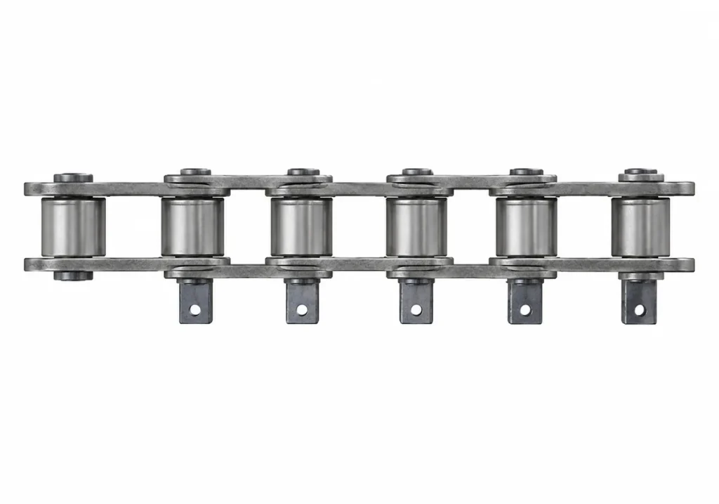
The Chain Section is the repeating chain assembly between flight positions. In the K201B model it is identified as K201B01; in K207B it is K207B01. The chain section brings together plates, bush and pin elements into the jointed structure that articulates around the conveyor path.
During identification, photograph the chain section from both side and top views. The outer profile alone may not reveal differences in plate construction, pin extension, or attachment details.
Inner and Outer Links
The K201B secondary structure identifies K201B02 Outer Link and K201B03 Inner Link. K207B identifies K207B02 Outer Link and K207B03 Inner Link, and also includes K207B04 Scraper Outer Link. The model-specific naming is useful when reviewing photographs or a drawing because it shows that not every outer-link position performs the same attachment function.
Link inspection should record visible deformation, unusual edge contact, damaged bores or attachment areas, and any mismatch in replacement parts. This page does not publish numerical wear limits; those belong to the approved maintenance specification.
Bushes and Pins

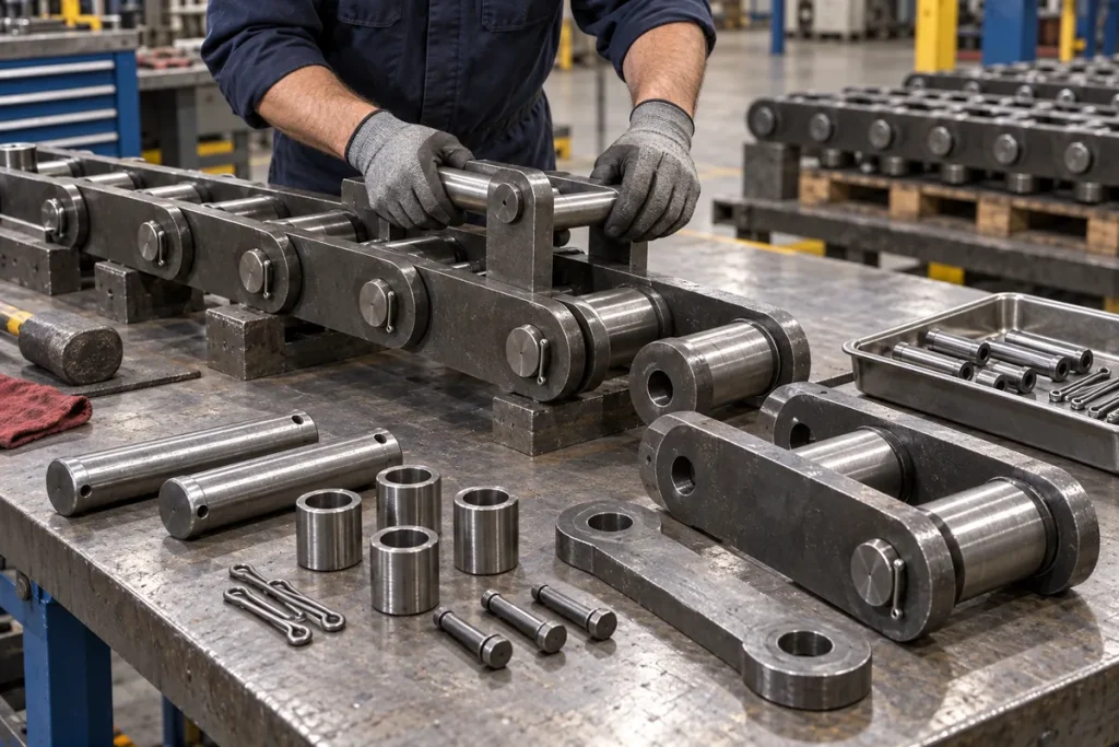
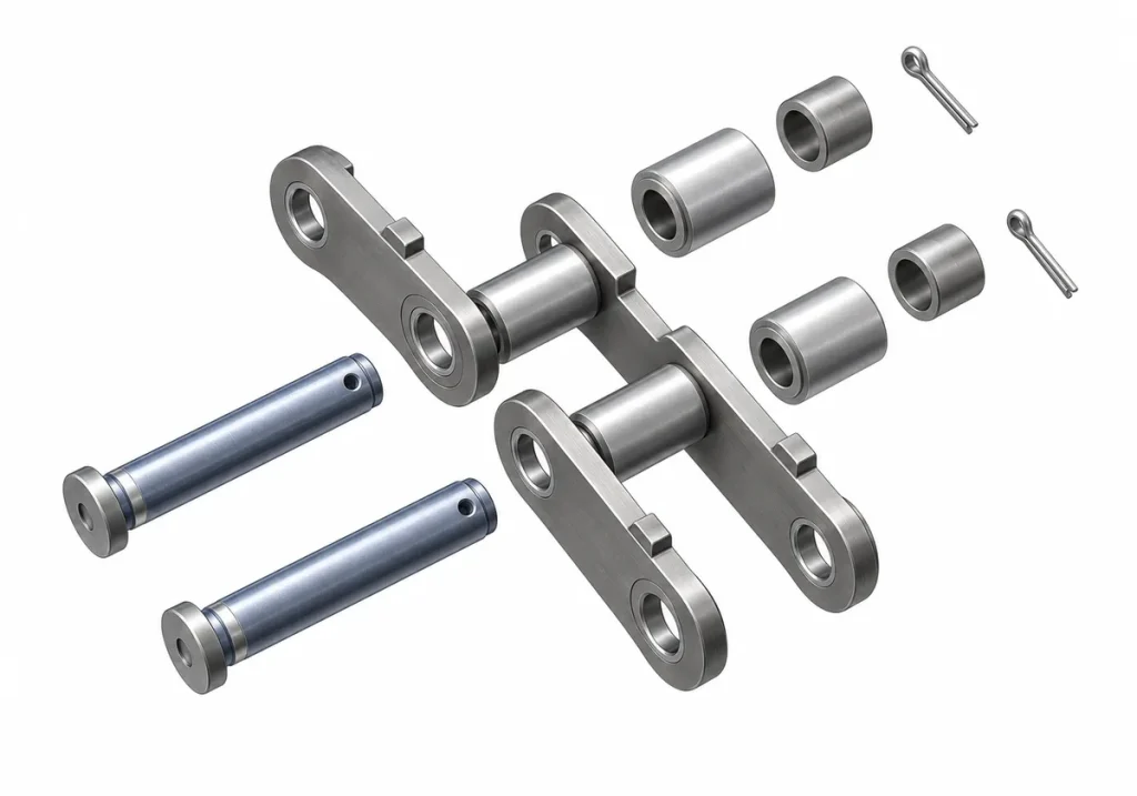
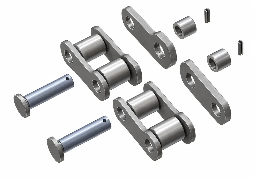
Bushes and pins form the articulated joint. K201B documents K201B003 Bush, K201B004 Pin, K201B005 Locating Bush, and K201B006 Spring Pin. K207B documents K207B004 Bush, K207B005 Pin, K207B006 Extended Pin, and K207B007 T-Pin.
These differences are valuable identification clues. If an unknown chain has an extended-pin or retention arrangement similar to K207B, that observation should be recorded, but it is still not enough to claim a model match without checking the rest of the chain geometry.
The K Series family source identifies special heat-treated pins as a feature. It does not provide a K201B- or K207B-specific hardness, case depth, or heat-treatment recipe, so those values should be requested from the approved technical specification when needed.
Flight Section


The Flight Section carries the scraper/flight elements that move material through the conveyor. K201B identifies K201B04 Flight Section; K207B identifies K207B05 Flight Section. Because the flight assembly controls material contact and overall conveyor width, its geometry is a major replacement-selection input.
Photograph the flight from the front, side, and connection areas. Record scraper width, spacing, and the relationship between the flight section and the chain links. If a flight is bent or damaged, use an intact flight as the dimensional reference whenever possible.
Scraper Head and Scraper Plate
The K201B component tree identifies K201B007 Scraper Head and K201B008 Scraper Plate. K207B identifies K207B008 Scraper Head and K207B009 Scraper Plate. the technical data also describes K Series customisation options that can include different scraper-bar heads, which reinforces the need to document scraper geometry during custom or replacement work.
Do not assume that a scraper head or plate from one chain configuration can be fitted to another simply because the overall chain pitch is similar. Attachment geometry, width, and load path should be confirmed from the drawing.
K201B vs K207B Component Trees
| Function | K201B | K207B |
|---|---|---|
| Chain Section | K201B01 | K207B01 |
| Outer Link | K201B02 | K207B02 |
| Inner Link | K201B03 | K207B03 |
| Scraper Outer Link | – | K207B04 |
| Flight Section | K201B04 | K207B05 |
| Outer Plate(s) | K201B001 | K207B001 / K207B002 |
| Inner Plate | K201B002 | K207B003 |
| Bush | K201B003 | K207B004 |
| Pin | K201B004 | K207B005 |
| Additional joint items | Locating Bush; Spring Pin | Extended Pin; T-Pin |
| Scraper Head | K201B007 | K207B008 |
| Scraper Plate | K201B008 | K207B009 |
The table is a structural reference. It does not state that every identifier is separately stocked or sold. Component-level supply should be confirmed by RFQ.
What to Include in a Component RFQ
When a single component appears damaged, send the complete chain model if known, the component identifier if readable, photographs of the component in its assembled position, dimensions, quantity, and the overall chain configuration. A close-up of the damaged part without the surrounding assembly can be misleading because attachment and joint relationships may not be visible.
For an unidentified chain, include pitch, unit length, scraper width, photographs of the complete chain and flight arrangement, and any drawing. This allows the component request to be tied back to a chain configuration rather than treated as a generic spare part.
Reading an Exploded View Without Turning It into a Parts Assumption
An exploded view is useful because it shows how plates, bushes, pins, retention parts, and scraper components relate to each other. It should not be interpreted as proof that every item is a separately orderable spare. The product drawing and quotation scope decide whether a component is supplied individually, as part of a chain section, or only within a complete assembly.
When an RFQ refers to a component identifier, include a photograph of where that component sits in the complete chain. This prevents confusion when similar names are used on different models. For example, a “pin” may differ in length, retention method, or role even when the plain-English description is the same.
Model-Specific Joint Details
K201B and K207B provide a useful example of model-specific joint construction. K201B includes a Locating Bush and Spring Pin in its documented tertiary components. K207B includes an Extended Pin and T-Pin. Those names tell the reviewer what to look for during identification, but they do not by themselves define dimensions or interchangeability.
If an installed chain appears to combine features from different configurations, document the assembly as found. Do not “normalise” it to the expected model. A mixed repair history, field modification, or incorrect previous component may explain the observation, and the engineering review needs to see that evidence.
Component Condition vs Component Identity
Two separate questions should be recorded during inspection: What component is this? and What condition is it in? Identity is established from model/drawing evidence and geometry. Condition is established from the current visual and dimensional inspection. A worn component does not become a different part number simply because its dimensions have changed in service.
For joint components, note visible retention condition, deformation, unusual movement, or damage. For plates and links, note abnormal contact, distortion, or visible damage. For flights and scraper elements, note geometry change, looseness, and uneven contact. Numeric acceptance limits belong to the approved maintenance specification, not to an unsupported web table.
Preparing a Component Comparison Sheet
For complex enquiries, create a simple comparison sheet with one row per observed component. Include the chain model if known, component name/identifier, photograph reference, measured features, drawing reference, observed condition, and open questions. This is particularly useful when a customer wants several replacement components and the complete chain identity is not yet confirmed.
The sheet also helps prevent parts from different chain runs or machines being mixed during an RFQ. If samples are removed from the site, label each sample with its equipment and position before shipment.
When a Complete Chain Review Is Better Than a Parts RFQ
A component-only enquiry should be escalated to a complete chain review when the chain model is unknown, multiple joint/flight parts are damaged, the installed configuration differs from the drawing, or chain/sprocket engagement problems are present. In those cases, quoting a single visible component may solve the immediate symptom while leaving the underlying configuration question unresolved.
Attachment and Retention Features Matter During Identification
Feeder breaker chain identification should include the way components are retained and attached, not just the broad names of links and flights. Pins, bushes, locating features, spring pins, T-pins, scraper outer links, and other attachment details can distinguish one configuration from another. The K201B and K207B component trees demonstrate why a component-level review is useful: the two products share common chain concepts, but their specified structures are not identical.
When inspecting an existing assembly, photograph these features before disassembly whenever the site procedure allows. A loose pin or damaged retainer can look very different after the chain is removed, and a repair can hide the original arrangement. Keep images of both the complete joint and the individual component if it is later removed.
Do not assign a component code from appearance alone. Use a component number only when the model/drawing relationship supports it. Otherwise describe the feature generically – for example, pin, bush, flight attachment, or retaining feature – and send the geometry for review.
Compare Intact and Damaged Components Separately
A damaged part is valuable evidence of failure or wear, but it may be a poor dimensional reference. If a scraper head is bent, a plate is worn thin, or a pin has been damaged, photograph the condition and then compare it with an intact component from the same chain run when available. This separates condition evidence from design evidence.
For a broken joint, retain the mating parts and record their original relationship. For a worn bush or pin, note the location in the chain path and whether nearby joints show the same condition. For a flight assembly, compare both sides and record any repair welds, replacement plates, or non-original fasteners that could affect identification.
A component inspection should therefore answer two different questions: What is this part supposed to be? and What has happened to this particular part in service? Combining those questions can lead to an incorrect replacement drawing.
Component Traceability in a Replacement RFQ
A component-level RFQ should tie every requested part back to a chain model or controlled drawing. For a known K201B or K207B assembly, state the model and the component name/code where it is directly supported. For an unknown chain, provide photographs, measurements, mating geometry, and the parent assembly rather than borrowing a code from the closest-looking model.
Include quantity and clarify whether the request is for individual service components, a complete chain section, a flight section, or a complete chain assembly. The existence of a component in a catalogue structure does not by itself establish that every component is sold separately; commercial availability should be confirmed during quotation.
For custom configurations, use a drawing that shows the component’s interfaces and relationship to the surrounding links. Mark critical dimensions and any customer-controlled material, heat treatment, coating, inspection, marking, or documentation requirement that has been supplied. Leave unspecified technical values open for engineering confirmation rather than filling them from a different chain family.
Component Review Checklist
Before releasing a component enquiry, confirm the parent chain or application, the component role, the intact geometry, connection/retention method, quantity, and evidence source. Add photographs from more than one angle when a single view cannot show the interface clearly. If the part is worn or broken, include an intact reference when possible and identify which measurements came from which part.
This approach creates a traceable path from machine to chain to subassembly to component. It also prevents a small part request from losing the context needed to verify fit.